Marking Critical Points
Currently in C3D there is no way to label the elevation of a profile by simply selecting a station or keying one in. Instead, you must enter in both the station and the elevation in order for the station and elevation label to work. This becomes even more problematic, as osnaps like intersection to not work on a profile. So, that leaves you with a couple of options; 1.) trace over the FG profile with a line or polyline, 2.) copy the profile and explode it twice. I'm sure that there are other ways to label the finished ground at a specific station; VBA comes to mind, but nothing really "out of the box".
Here in Texas our roads are parabolic and we design off the top of curb, so this step-by-step guide might need to be tweaked for the roads in your region.
Next, create the assembly of your liking. Notice how I have left the curb subassembly in the assembly that is used to model the intersection. This can be removed later for final modeling, but must remain present for the time being.
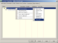
Create a corridor from the FG profile and assemblies, but make sure you create a surface from the curb link.
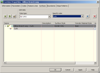
It is probally a good idea to throw a boundary on the surface too.
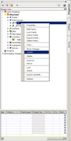
Next, we will add points to the profile view to mark the various critical points. I went ahead and created a point group called "CR" (curb return/critical points) and assigned the point group a marker style consisting of a custom marker, a line in this case.
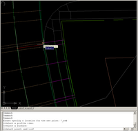
Points>Create points>Miscellaneous:manual
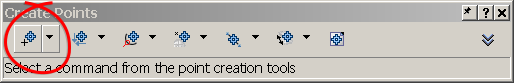
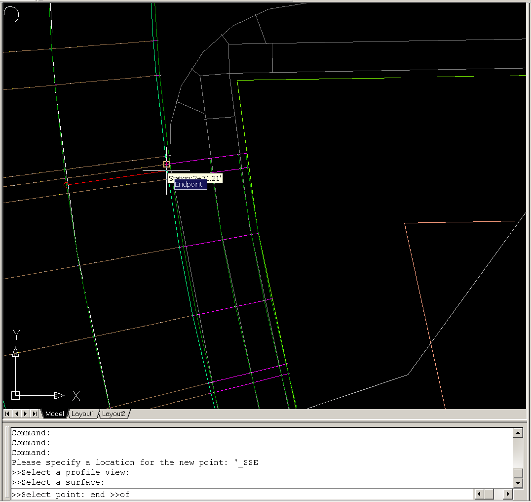
Place points with the transparent command: Profile Station and Elevation from Plan
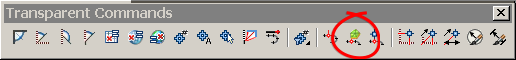
After selecting the transparent command you will be prompted to select a profile view. Select the subject profile view. Next, C3D will want to know what surface to pull elevations from. This is where you will select the corridor surface composed of the curb links. Finally, C3D will prompt you to select a point. This is where you can select every curb return, intersection, or critical station along the corridor alignment. No need to "pre-label" the critical stations inorder to manually key them in.
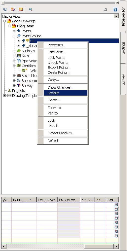
Next, update the point group, CR in this Case.
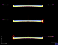
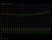
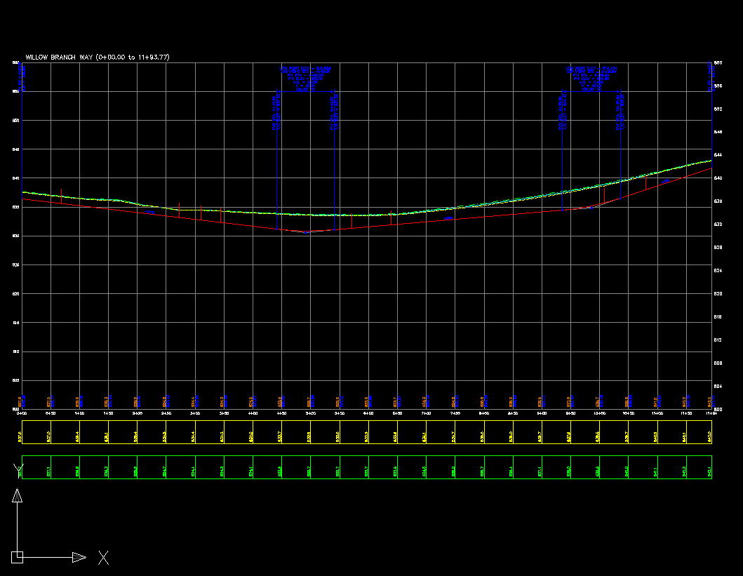
After updating, you will notice that your profile view has been marked with points at the critical stations you have choosen and they are at the correct elevation!!
Enjoy!!
p.s. Being as this is my first attempt at a blog or a write up, any and all comments and suggestions are welcome.
Here in Texas our roads are parabolic and we design off the top of curb, so this step-by-step guide might need to be tweaked for the roads in your region.
This will be a 2 part write up. Today's guide is a walk-thru in marking critical points in your profile view.
Marking The Profile
Start with laying out your finished ground profile

Next, create the assembly of your liking. Notice how I have left the curb subassembly in the assembly that is used to model the intersection. This can be removed later for final modeling, but must remain present for the time being.

Create a corridor from the FG profile and assemblies, but make sure you create a surface from the curb link.

It is probally a good idea to throw a boundary on the surface too.

Next, we will add points to the profile view to mark the various critical points. I went ahead and created a point group called "CR" (curb return/critical points) and assigned the point group a marker style consisting of a custom marker, a line in this case.
Points>Create points>Miscellaneous:manual

Place points with the transparent command: Profile Station and Elevation from Plan
After selecting the transparent command you will be prompted to select a profile view. Select the subject profile view. Next, C3D will want to know what surface to pull elevations from. This is where you will select the corridor surface composed of the curb links. Finally, C3D will prompt you to select a point. This is where you can select every curb return, intersection, or critical station along the corridor alignment. No need to "pre-label" the critical stations inorder to manually key them in.
Next, update the point group, CR in this Case.
After updating, you will notice that your profile view has been marked with points at the critical stations you have choosen and they are at the correct elevation!!
Enjoy!!
p.s. Being as this is my first attempt at a blog or a write up, any and all comments and suggestions are welcome.
posted by Matt Castelli at
9:07 AM
![]()
![]()

4 Comments:
Hi Matt. Have you worked with the profile bands? In the elevation band, you can toggle labeling vertical or hor geometry points, if my mind hasn't wondered too far off the path tonight...
PS-welcome to the blog world. I myslef just recently started a blog as well. Maybe we should include recipies for salsa to differentiate ourselves... :)
By Anonymous, at 7:55 PM
Hi... nice first blog. I have oslo recently started a blog and find it difficult to know how much detail to include or not. Also, sometimes my assumptions may not be someone else's because of locality regulations or even "rules of thumb."
I was confused at first reading this post. I couldn't figure out how you were getting the correct elevation at both the intersection points and at curb returns. Then I realized that your crown matches your curb elevation. This is typical in some states but in others, regardless of the parabolic pavement. For instance, Delaware uses a straight lane section with 1/4" per foot slope (or 2.08%) which gives you about a 3" crown. Then, there is other curb heights (mountable, laid back, depressed) based on the type.
Obviously, this is more detail than you're trying to relay in the blog. Thanks for helping me understand a new way of labeling points in a profile!
By Anonymous, at 8:19 AM
Actually, my assembly has a 5” crown and a 6” curb. The key to having the points label/insert correctly on the FG profile, is to make sure the top of curb matches the baseline insertion/ground reference point. So, using this method, the shape of your road does not matter, so long as the top of curb is placed properly within the assembly. For example, I could change my assembly to use a 1” crown or 3” crown and my top of curb surface would not be affected. If you want, I’ll add an additional detail image if I didn’t explain things clearly.
By Matt Castelli, at 9:12 AM
thanks for a great and informative blog, matt!
By Dana, at 5:29 PM
Post a Comment
<< Home