Tapping Into Civil 3D

Wednesday, May 14, 2008

Match Maker

So I was playing around in C3D '09 and stumbled upon something pretty sweet. Match Properties now works on object styles! No special command needed, just click on the paint brush or type in MA at the command line and use like normal!

Selected northern alignment first...


Southern alignment now matches.


I have not had any luck getting label styles to match, but I'll be looking forward to that feature in future releases.

Tuesday, March 06, 2007

Natural Ground! Report!

Nothing to report Sir!!

That is what you'll notice too when you try and run the Profile-Incremental Stationing Report.

The VBA report is supposed to have the ability to list "PVI stations and elevations of the selected existing or finished ground profile at regular intervals, at critical geometry points, and crest and sag curve points." However, any profile created from a surface does not show up in the list of profiles in the drawing.


Proof that there are profiles in the drawing.


Come to find out the VBA routine only works on finished ground profiles, contrary to what the dialog box tells us. So we need to figure out how to get a FG profile to match our existing ground profile, with out tracing ;-)

It's actually pretty simple.
Step 1.) Create an assembly and add a marked point to it.


Step 2.) Create a corridor; use the alignment that the surface profile was created from as the baseline, use the surface profile as the profile, and use the simple assembly from step one. Your frequency really shouldn't matter so long as you have the option "At Profile Geometry Points" on.


Step 3.) Now that you have your corridor built...


Extract a profile from the corridor

C3D will prompt you to select a feature line; this should be easy since there is only one! After picking on the lone feature line, give the new profile an appropriate name and style.


After clicking OK, you can go to your profile view and verify that the new profile exactly matches the original.


Now, go back and run the report and you should see the extracted profile ready to have a report run on it.


-Enjoy!!

p.s. Looking ahead to '08, the same procedure will be necessary.

Wednesday, November 08, 2006

Right Click, Transparency

Scott and I were at a local surveying firm today showing the ins and outs of C3D to some new users. Obviously, being a survey firm, they would need to know how to draw a line by direction so we showed them the "Bearing Distance" button on the transparent command toolbar. One of the users then asked, "Can I get to that with a right click?" Makes sense...almost everything else can be accessed through a right click. However, out-of-the-box c3D does not allow you to access the transparent commands with a right click. But, just because it doesn't come OOTB, doesn't mean we can't add it in!

Type CUI at the command line to bring up the Customize User Interface. Expand Shortcut Menus and locate "Context menu for command mode"


Once you've located the menu, right click and add a sub menu.


In the lower left corner of the CUI dialog box there is a section call "Command List:" this is where we will locate the commands to drag into our new sub-menu. In order to help find the commands, sort the commands by Source. After sorting, scroll down until you find "Angle Distance", this will be the beginning of the transparent command list. Now just left pick on a command and drag it under the new sub-menu. Add as many or few commands as you like.


When your all done, you should have something that looks like this.


-Enjoy!

Monday, November 06, 2006

Not Everything Flows Downhill!

Water Lines, Gas Lines, Electrical Conduit and everything else that doesn't have to flow down hill can be a bit tricky to show using pipes in C3D. That doesn't mean it's not possible though. Follow along to see how.

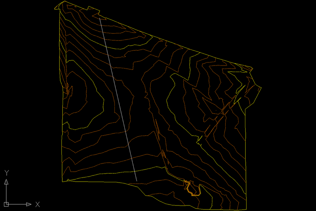
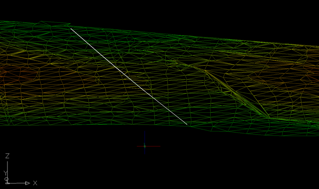
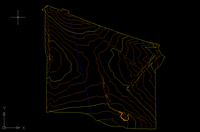
I start out by drawing a polyline across my surface. This represents the centerline alignment of my water line.


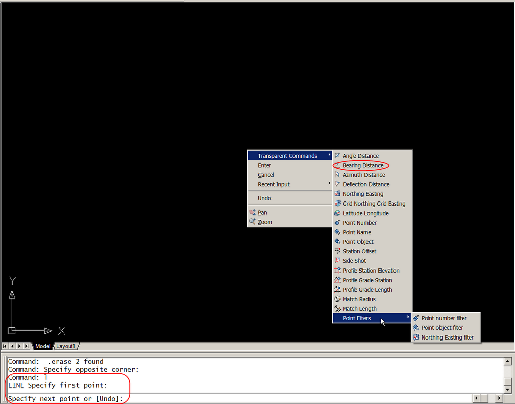
Turn the polyline into a feature line.

I like to keep my drawings organized so I choose to create an "H20-1" site to place the feature line in. Style is not important and erasing the existing entities will not affect the end result.


Project the feature line to the Surface.


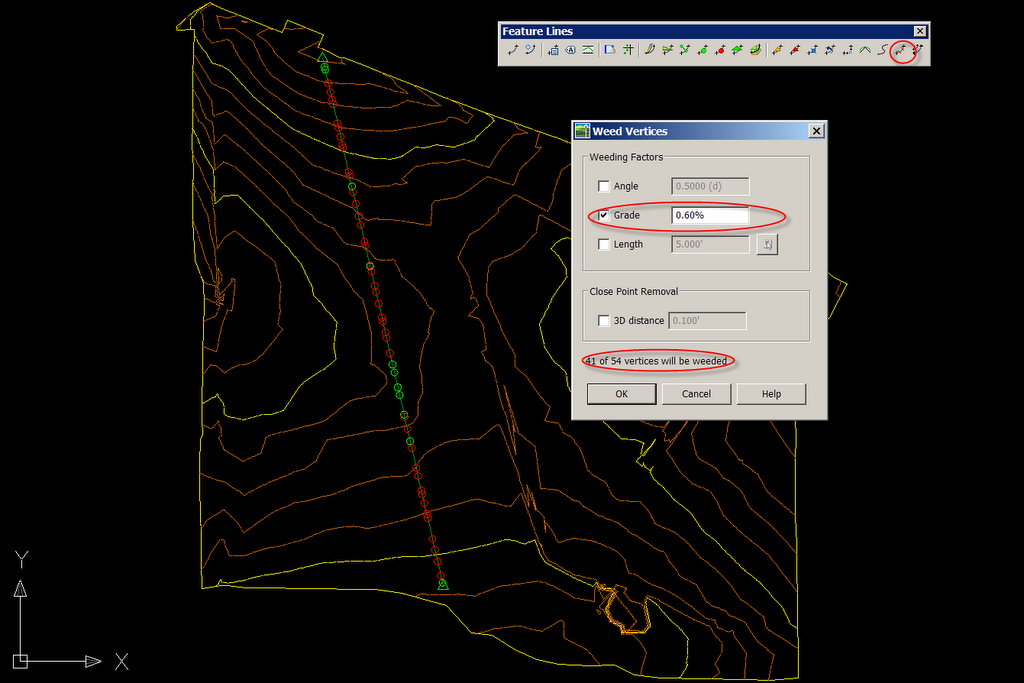
Notice now that we have quite a few vertices in our feature line, in fact, too many! We need to "weed" out some of those vertices to prevent our pipe network from being a bunch of little pipe segments. To accomplish this, we will use the "Weed vertices" button on our feature line tool bar. I choose to set the criteria to %0.60, you may find that a different percentage or a combination of angle and distance yields a better result for your situation.


Select the Feature line, right click, and go to the elevation editor. This is where you will use the Lower Incrementally button to set the depth of your water line. In my case, 4' below natural ground.*

*The feature line will define the center of the pipe. So, since I lowered my feature line 4' and I am building a 12" water line, I will have 3 1/2' of cover.


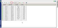
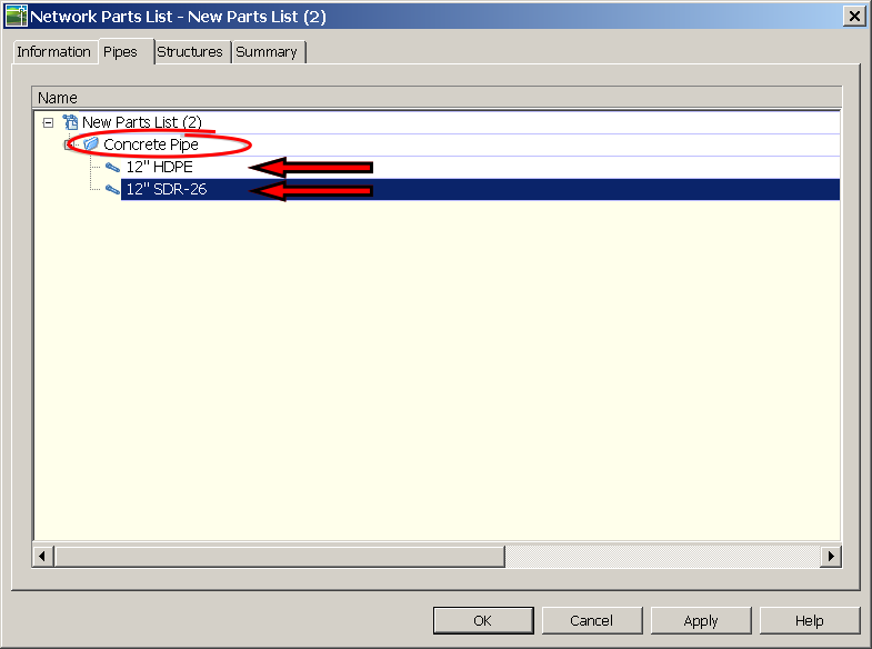
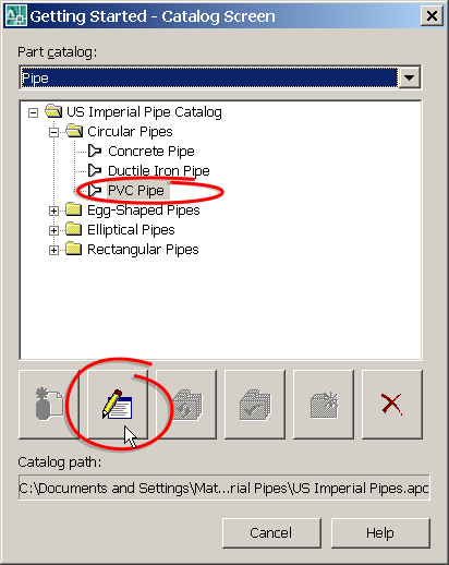
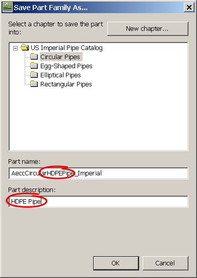
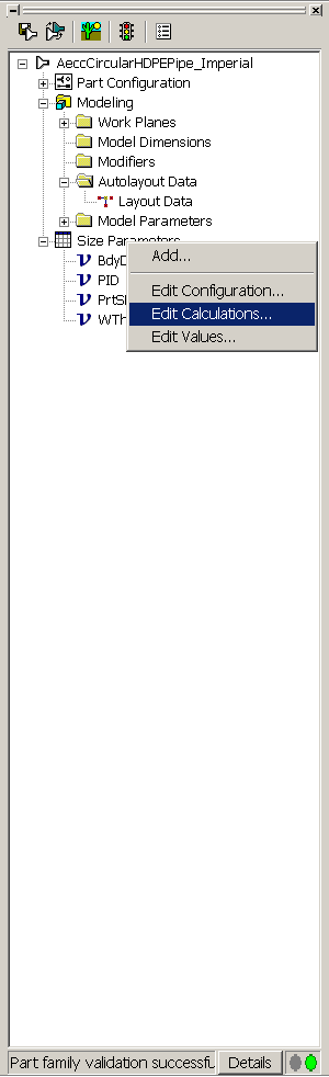
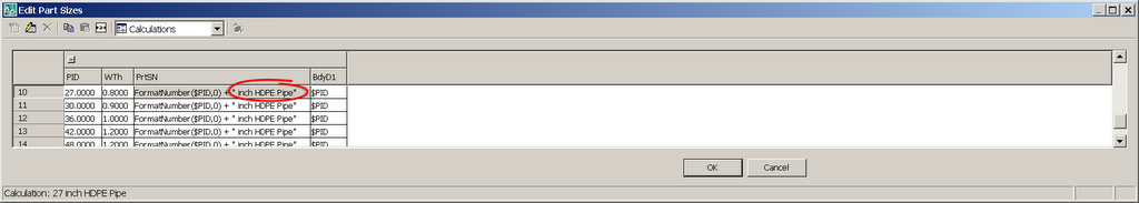
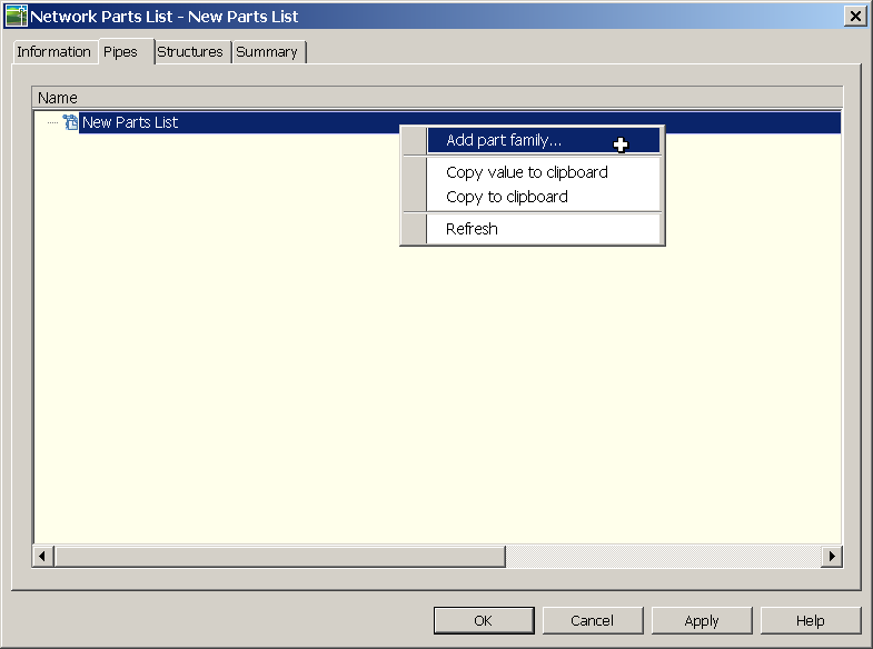
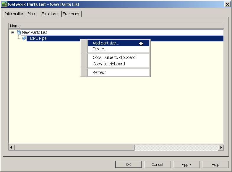
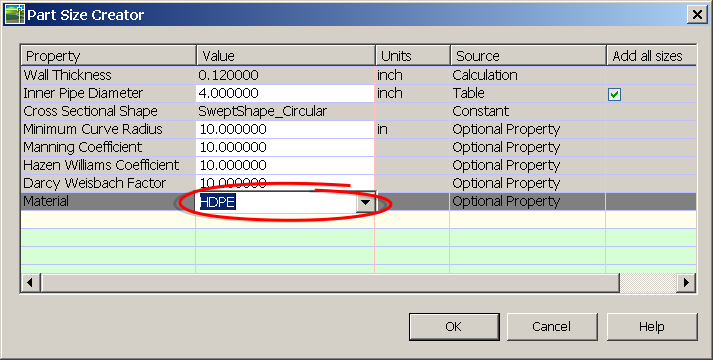
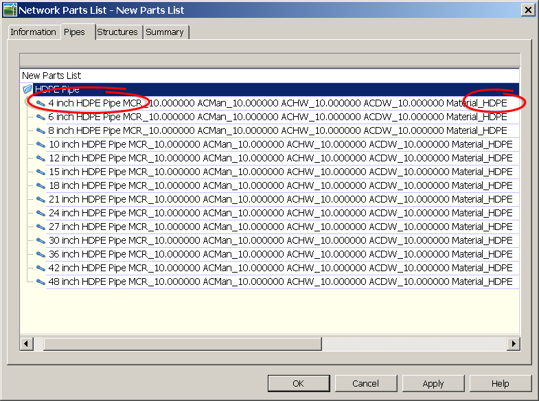
The next step is to create a parts list from which our network will be created. On the pipes tab add waterever pipe material and size of pipe that suits your design need. If you can't find the material you like, look here. On the structures tab DO NOT add any structures. Simply modify the style and the rules being used.


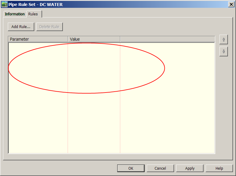
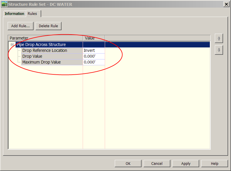
The rules being applied to the pipes and structures are key in this process. Here is how they should be set up.

Pipes:

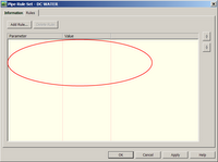
No, there is no mistake here. I've actual created a rule set that has no rules.
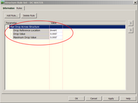
Structures:


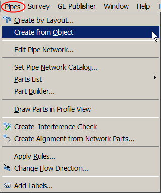
Before we turn our feature line into a pipe network we need to edit our "CreateNetworkFromObject" command setting.


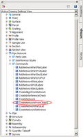
There are three setting that need to be adjusted:
Default parts List, Pipe Default Rules, Structure Default Rules


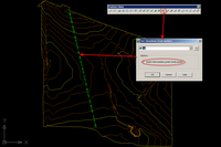
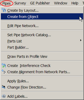
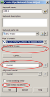
With the settings set...we can now turn our feature line into a pipenetwork


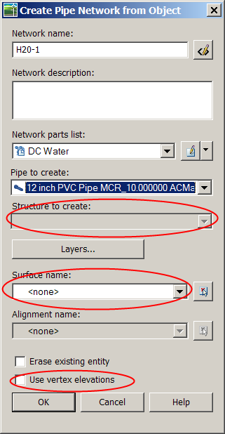
After selecting the feature line the below dialog box will show up. Notice that the option to choose a structure has been grayed out. Also be sure NOT to select a surface and make sure "Use vertex elevations" is NOT checked.


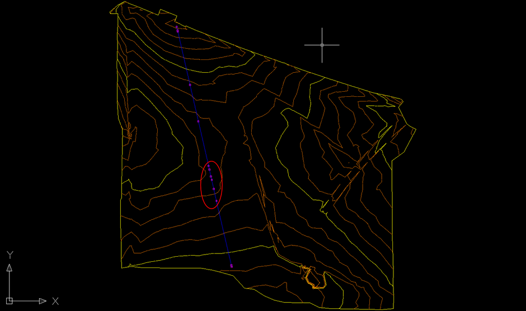
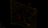
At first glance, it appears that we have now placed structures at all the remaining vertices....


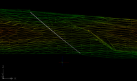
But, as we roll the model up into 3-D, we see that indeed, no structures were placed in our network


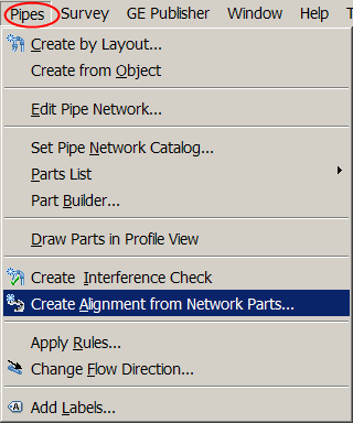
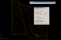
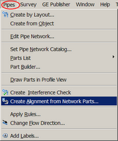
At this point we have completed laying out our network, but we still need to get it into a profile. And what's the first step of creating a profile? Well, we need an alignment, so let's create an alignment from network parts.


Choose the first "structure", then the last "structure", and then hit enter to confirm the selection.

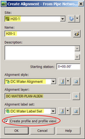
Well organized sites and thought out names for objects and styles make it easy to breeze through dialog boxes like this. Make sure to check "Create profile and profile view"

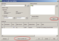
Add the Natural ground surface, and then draw it in a profile view.


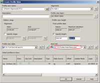
Adjust the profile view to your liking.


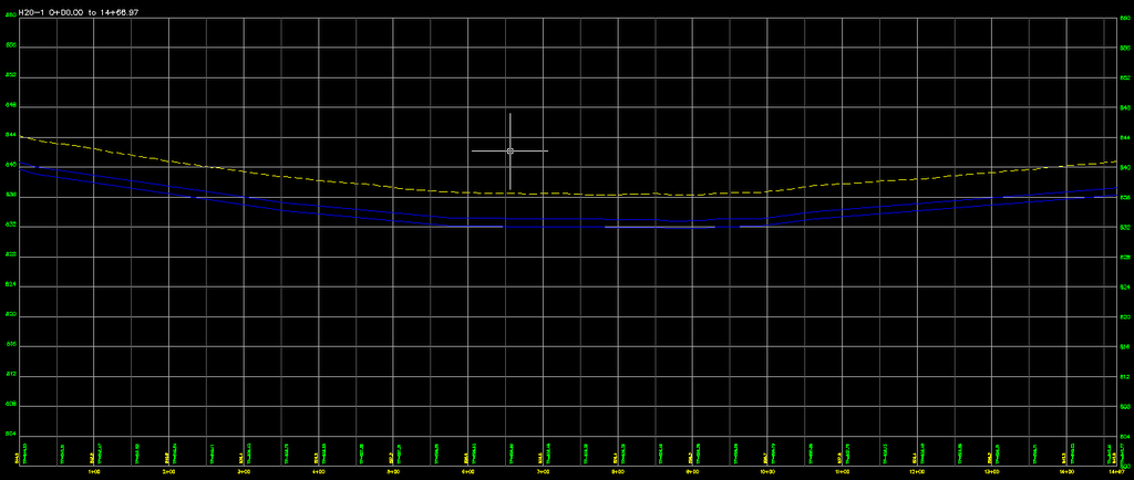
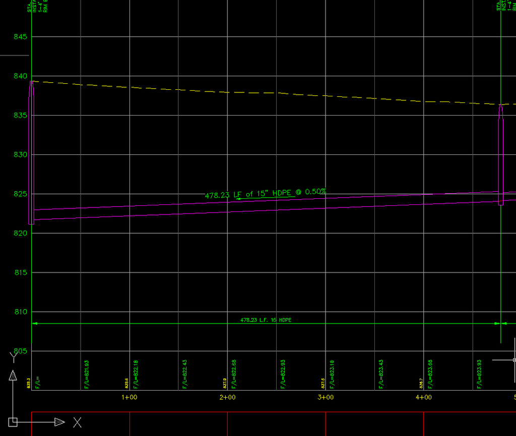
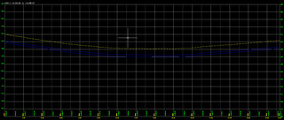
Place the profile view somewhere in your drawing and you should have something that looks like this!


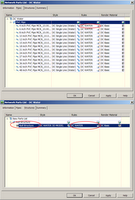
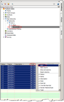
The final step is to clean up the plan view. Browse to the structures of the H20-1 network in the prospector. In the preview pane select all the structures, move your cursor to the heading of the styles column, right click and select edit. Select and more appropriate style, one that does not use a block in plan or profile view.


Looking back at the plan view you can see that everything looks as expected.


Look for some upcoming posts as we take this waterline profile a little closer towards a construction document.

Wednesday, September 13, 2006

It's OK to be Materialistic

Reinforced Concrete
Corrugated Steel
ABS Plastic
Ductile Iron
PVC

The above are the materials that C3D gives you to describe the pipes inside your pipe network. However, as most of you already know, in the real world we use a much wider variety of materials in our projects.

Current workarounds to having your labels display properly, even though the actual material of the pipe is incorrect:

1.) Edit the description of the pipe inside of your part list.

Then you can simply pull the description component inside your your label.

2.) Hard code, or type in a piece of text inside your label.

Both of the above ways are not linked to the pipe model. So if the material or pipe size where to somehow change, said change would not be reflected in the label.

So how can you add more materials to your current list and have them update dynamically. Easy...just type in a new material!!! That's it!

The below process also steps you through how to create a new part family to better organize your new materials.

Step 1. Launch partbulder. Type it in or select it from the pipes pull down menu

Step 2. Select an existing part family to modify.


Step 3. Save part family as..

Step 4. Rename the new family

Step 5. Edit the calculations

Step 6. Notice the name that is being used in the PrtSN (Part Size Name) Column.


Double click on one of the cells under the PrtSN column to bring up the Calculation Assistant. Here you can edit the name from PVC to whatever, in this case HDPE.

End result:


Step 7. Validate and save the part family


Step 8. Create a new parts list and add a family.


Step 9. Choose the freshly created part family.


Step 10. Add a part size


Step 11. Now we should be at a dialog box that looks familiar to everyone. This is where we choose our part size and it's also where we make sure our parts are going to referencing the correct material (See Dana's blog here). But what if we want to use a material other than the five listed...no problem, just click inside the cell and type in a new pipe material.

After choosing your pipe size(s), OK out of the dialog box.

End result:


So what does this mean? I no longer have to pull the description of my pipe in my label (which isn't even possible when dealing with a pipe band), instead I can pull the Dia. and Material and achieve the same result. Except this time, the label is dynamic to part size and material.


Final Product:


-Enjoy

p.s. So yeah, I know it's been a while since I posted. I will try to post a little more regularly from now on to make it worth people's time to check out my posts.