Natural Ground! Report!
Nothing to report Sir!!
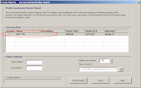
That is what you'll notice too when you try and run the Profile-Incremental Stationing Report.
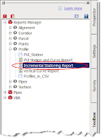
The VBA report is supposed to have the ability to list "PVI stations and elevations of the selected existing or finished ground profile at regular intervals, at critical geometry points, and crest and sag curve points." However, any profile created from a surface does not show up in the list of profiles in the drawing.
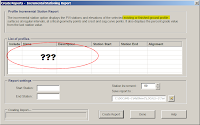
Proof that there are profiles in the drawing.
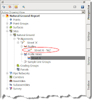
Come to find out the VBA routine only works on finished ground profiles, contrary to what the dialog box tells us. So we need to figure out how to get a FG profile to match our existing ground profile, with out tracing ;-)
It's actually pretty simple.
Step 1.) Create an assembly and add a marked point to it.
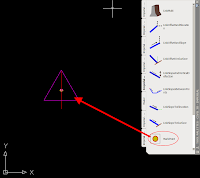
Step 2.) Create a corridor; use the alignment that the surface profile was created from as the baseline, use the surface profile as the profile, and use the simple assembly from step one. Your frequency really shouldn't matter so long as you have the option "At Profile Geometry Points" on.
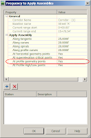
Step 3.) Now that you have your corridor built...

Extract a profile from the corridor

C3D will prompt you to select a feature line; this should be easy since there is only one! After picking on the lone feature line, give the new profile an appropriate name and style.
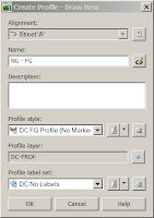
After clicking OK, you can go to your profile view and verify that the new profile exactly matches the original.

Now, go back and run the report and you should see the extracted profile ready to have a report run on it.
-Enjoy!!
p.s. Looking ahead to '08, the same procedure will be necessary.
That is what you'll notice too when you try and run the Profile-Incremental Stationing Report.

The VBA report is supposed to have the ability to list "PVI stations and elevations of the selected existing or finished ground profile at regular intervals, at critical geometry points, and crest and sag curve points." However, any profile created from a surface does not show up in the list of profiles in the drawing.

Proof that there are profiles in the drawing.

Come to find out the VBA routine only works on finished ground profiles, contrary to what the dialog box tells us. So we need to figure out how to get a FG profile to match our existing ground profile, with out tracing ;-)
It's actually pretty simple.
Step 1.) Create an assembly and add a marked point to it.

Step 2.) Create a corridor; use the alignment that the surface profile was created from as the baseline, use the surface profile as the profile, and use the simple assembly from step one. Your frequency really shouldn't matter so long as you have the option "At Profile Geometry Points" on.

Step 3.) Now that you have your corridor built...

Extract a profile from the corridor

C3D will prompt you to select a feature line; this should be easy since there is only one! After picking on the lone feature line, give the new profile an appropriate name and style.

After clicking OK, you can go to your profile view and verify that the new profile exactly matches the original.

Now, go back and run the report and you should see the extracted profile ready to have a report run on it.

-Enjoy!!
p.s. Looking ahead to '08, the same procedure will be necessary.

1 Comments:
Sounds like a ridiculous amount of steps. Why doesn't Autodesk just correct the routine?
By Anonymous, at 6:32 AM
Post a Comment
<< Home