Adding LDT commands in C3D
If you have visited the discussions groups at all, you've heard that complaint/comment more than once. Well, there is simply no way to bring forward those commands. However, one can easily transfer over the toolbars and drop down menus from LDT into C3D. Once there, a quick modification of the macro inside of the CUI will have your menus and toolbars looking like LDT and working with the power of C3D. Follow along to see how.
As an example I've chosen the "Terrain: Edit Surface" toolbar. Why? Because almost every button on this toolbar has an equivalent command in C3D. Not every toolbar or pull down menu will work as nice, but if some of these basic commands can be brought over, it just might be that crutch that some of the more "hardened" end users need to make the transition.Start by firing up LDT and going to the CUI. Click on the transfer tab. On the right hand side open up the civil.cui located in ?:\Documents and Settings\USERNAME\Application Data\Autodesk\C3D 2007\enu\Support. Once the civil.cui file is open its a matter of drag and drop from one cui (land) to the other (civil).
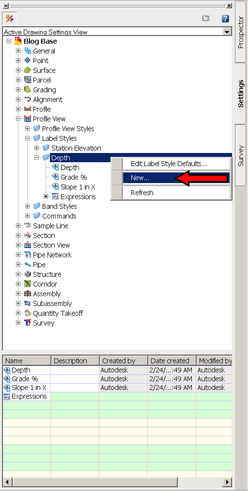
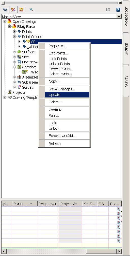
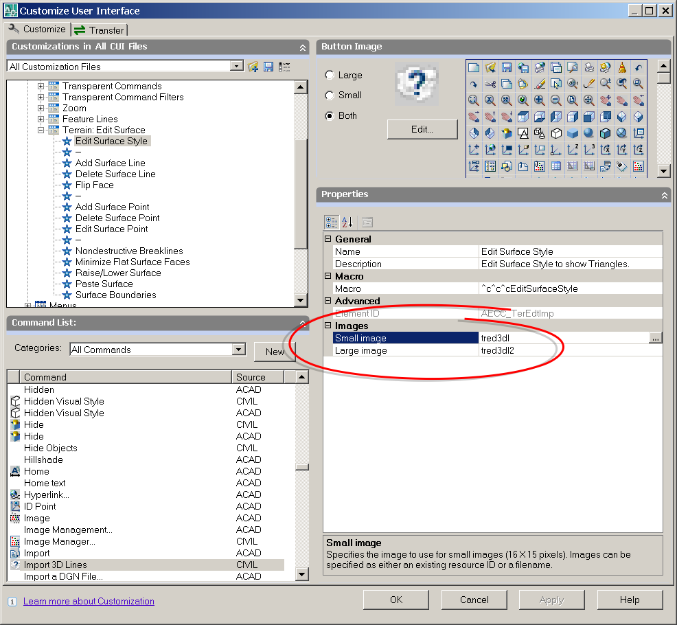
Now that we have the toolbar transferred from LDT to C3D, we can close down LDT and open up the CUI in C3D. Once in the CUI, browse in the toolbars until you find the "Terrain: Edit Surface" toolbar and expand it. By clicking on one of the commands under the toolbar you will populate the properties display pane. Here you will see the various fields we will need to edit.

The first button on the toolbar is "Import 3D lines". In LDT, it was necessary for one to import the 3d lines prior to editing the surface. In C3D it is only necessary for the current surface style to be displaying the triangles and/or points. I have chosen to populate this button with the EditSurfaceStyle command. This will allow the user to quickly access the surface style dialog box and turn on the triangles. EditSurfaceProperties would also be an acceptable command, so long as a surface style for editing has already been created. Wondering where I'm coming up will all these commands? Open up help and type in "Surfaces Command Reference", you will be given a result that contains a majority of the surface commands in C3D.
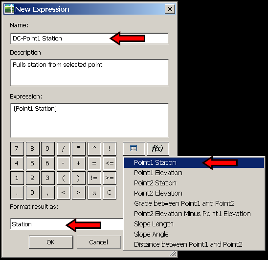
To edit the macro click on the contents of the macro in the display pane, then click on the ellipse.

Which will bring up the Long String Editor Dialog Box
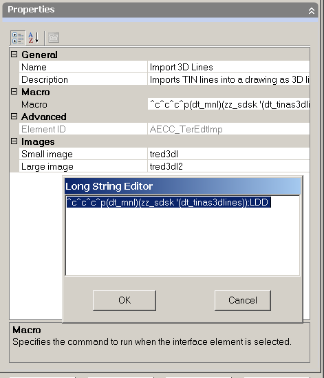
The macro should be composed as:

Notice how I've renamed the button and changed it's description.
The only thing we are missing now are the icon .BMPs. This is easier said than done, since all the .bmps are contained in a .dll instead of "free floating" .bmps like in years past. That's where Resource HackerTM comes into play. " Resource HackerTM is a freeware utility to view, modify, rename, add, delete and extract resources in 32bit Windows executables and resource files (*.res)." What that means to us, is the ability to extract all the nested bmps out of the .dll for use in our new toolbar and upcoming drop-down menu.
After downloading and extracting Resource HackerTM, start the program and open up the land.dll. You can find it here, ?:\Documents and Settings\USERNAME\Application Data\Autodesk\Autodesk Land Desktop 2007\R17.0\enu\Support. If your worried about messing up LDT, just make a copy for your use on the desktop. Once the file is open go to the Action drop down menu and Save All resources...

Choose a destination folder for all the soon-to-be extracted .bmps and the ".rc" file. Upon browsing to the chosen folder, you will find ~ 1630 bitmaps. They will be named "bitmap_1.bmp, bitmap_2.bmp, bitmap_3.bmp, etc." Decoding all these bitmaps is what the .rc file is for. Open up the .rc file with notpad and you will see something like this...

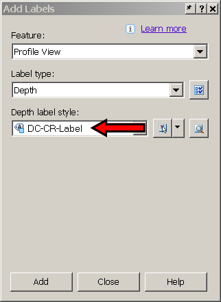
If we go back to the CUI, we can see which icons we are looking for. In this case "tred3dl" for the small image, "tred3dl2" for the large image. A quick search inside the notepad document will help you locate the various images. "tred3dl" happens to be "Bitmap_570.bmp". Edit the "Bitmap_570.bmp" file and rename it"tred3dl.bmp". You will need to repeat this process for every icon on the toolbar...I never said it was going to be fun or easy ;-)
After renaming the bmp, you will need to remap the icon location thru the cui. To keep things well organized, put all the renamed .bmps in the Icons folder located ?:\Documents and Settings\USERNAME\Application Data\Autodesk\C3D 2007\enu\Support\Icons
At this point, we have completed the process for the first button on the "Terrain: Edit Surface" toolbar. You will need to repeat this process for the remainder of the buttons.

Here is the list of macros I used to finish up the transfer:
Add Surface Line...........................^c^c^cAddSurfaceLine
Delete Surface Line......................^c^c^cDeleteSurfaceLine
Flip Face.........................................^c^c^cEditSurfaceSwapEdge
Add Surface Point.........................^c^c^cAddSurfacePoint
Delete Surface Point......................^c^c^cDeleteSurfacePoint
Edit Surface Point..........................^c^c^cEditSurfacePoint
Add Breaklines...............................^c^c^cAddSurfaceBreaklines
(^org. name of Nondestructive Breaklines)
Minimize Flat Surface Faces........^c^c^cMinimizeSurfaceFlatAreas
Raise/Lower Surface.....................^c^c^cRaiseLowerSurface
Paste Surface..................................^c^c^cEditSurfacePaste
Surface Boundaries.........................^c^c^cAddSurfaceBoundaries
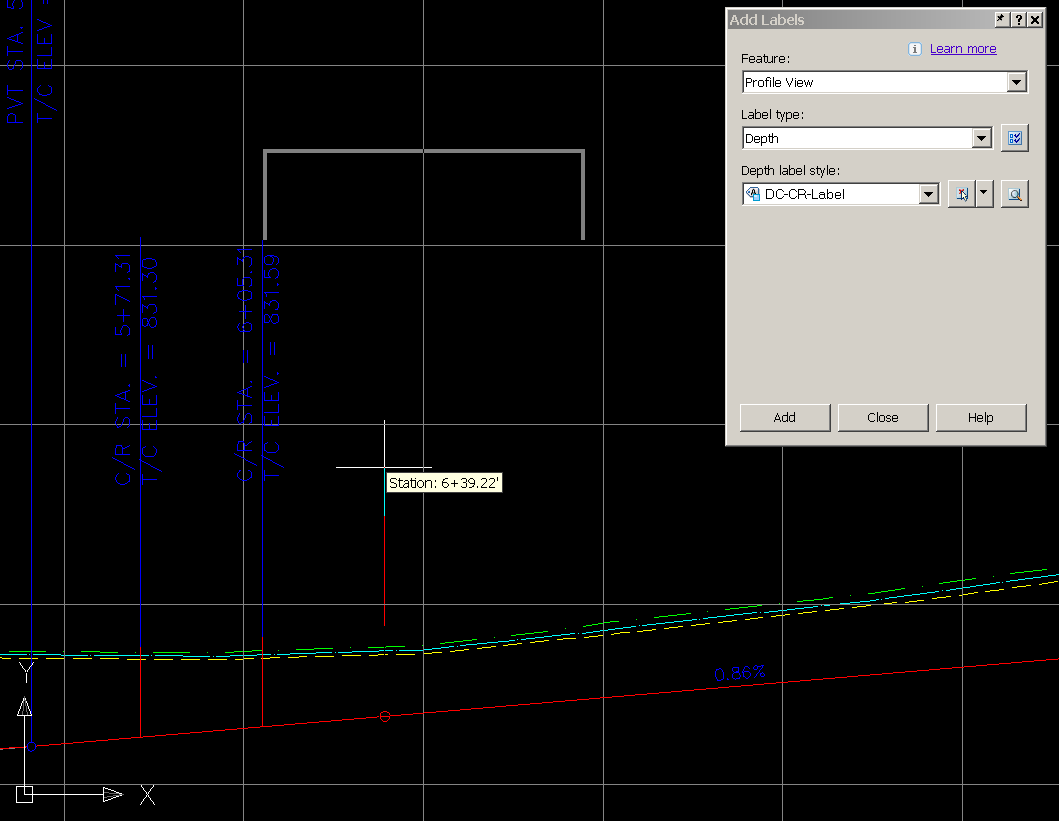
And when everything is said and done...

Enjoy!
As always, comments are welcome.
posted by Matt Castelli at
1:54 PM
|
1 comments
![]()
![]()